
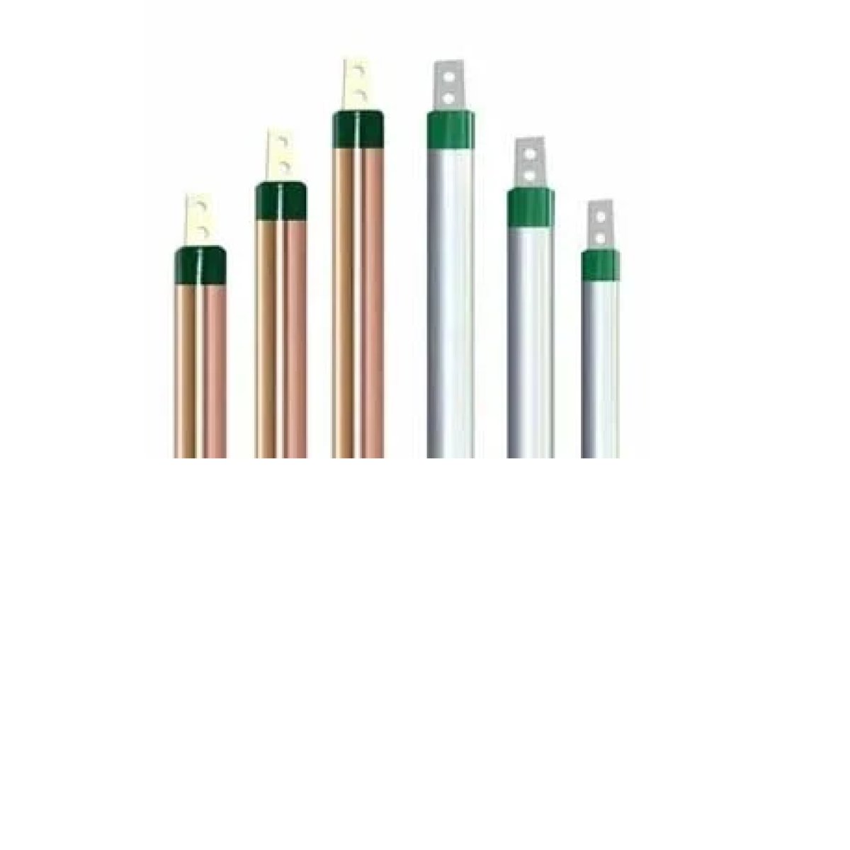
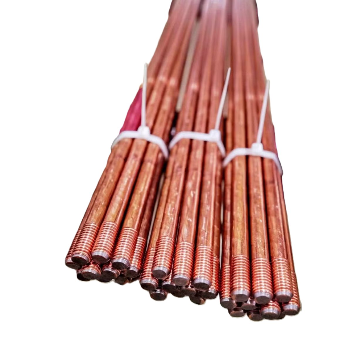
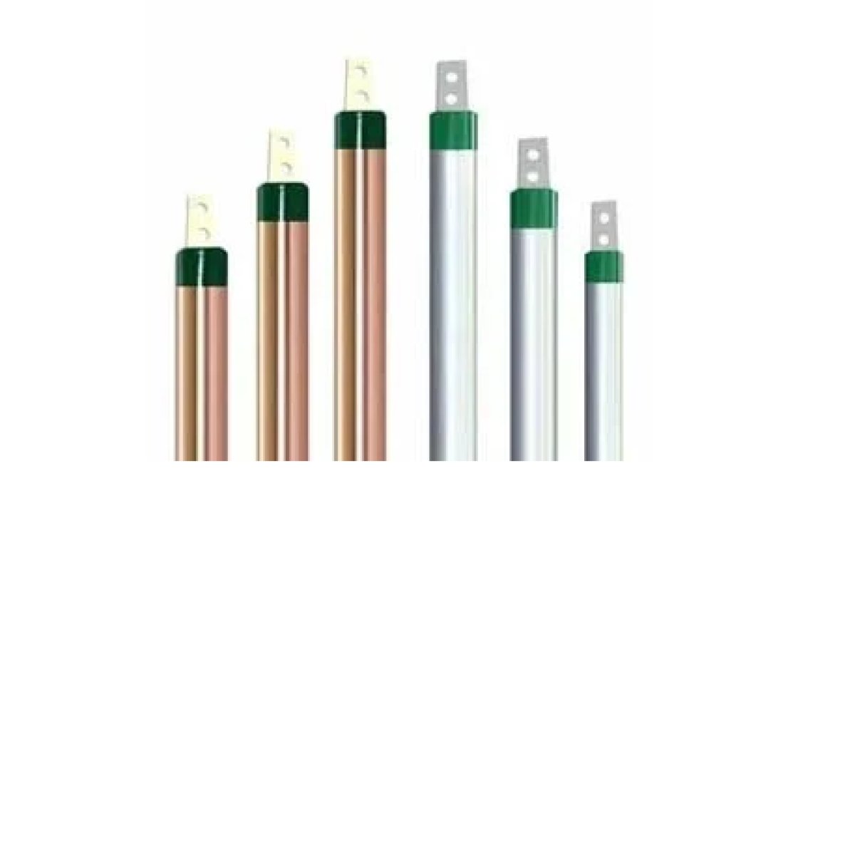
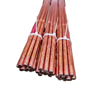
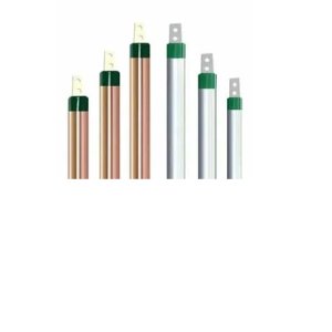
A Grounding Electrode (or Earth Electrode) is the final, subterranean component of an Earthing Protection System (EPS) and general electrical utility networks. Driven directly into or buried within the soil matrix, its primary engineering function is to establish a permanent, direct, and low-resistance electrical connection to the planet earth, allowing fault currents, lightning energy, and static charges to rapidly and safely dissipate into the ground.
1. Core Materials & Structural Types
Grounding electrodes must survive decades of chemical exposure inside varying soil conditions without corroding or losing electrical conductivity. Depending on geological terrain and facility scale, engineers select from three primary electrode configurations:
Driven Ground Rods: The most common commercial and residential configuration. These are typically 1.5 to 3 meters (8 to 10 feet) long rods driven vertically into the earth. They are manufactured as high-strength carbon steel cores molecularly bonded with an outer jacket of electrolytic copper (copper-bonded steel), providing mechanical rigidity for driving into dense soil paired with high electrical conductivity and corrosion resistance.
Grounding Plates: Utilized in shallow or rocky terrains where driving deep vertical rods is physically impossible. High-conductivity solid copper or hot-dip galvanized steel plates are buried horizontally at a minimum depth of 0.75 meters (2.5 feet) below the frost line.
Concrete-Encased Electrodes (The Ufer Ground): An exceptionally effective system that utilizes the building's structural foundation. A bare copper conductor or high-conductivity steel rebar matrix is embedded directly within the concrete footings touching the earth. Because concrete is naturally hydroscopic (it absorbs and retains moisture from the surrounding soil) and has a large surface area, it acts as an incredibly efficient, low-resistance electrical buffer.
2. Soil Resistivity & Resistance Optimization
The primary technical metric governing a grounding electrode is its Earth Resistance ($R_g$), which international standards (such as IEEE 142 and NEC Article 250) state should ideally be less than 25 Ohms for residential lines, and less than 5 Ohms or 1 Ohm for critical data centers and industrial substations.
The actual electrical resistance of an electrode is not determined by the metal rod itself, but rather by the surrounding soil chemistry. Resistance is optimized using three key engineering techniques:
Chemical Grounding Rods (CGR): Deployed in high-resistivity environments like desert sand or solid granite. These hollow copper tubes are filled with natural mineral salts that absorb ambient atmospheric moisture. The salt solution slowly leaches out through weep holes in the bottom of the tube, continuously conditioning the surrounding soil and keeping resistance consistently low regardless of seasonal droughts.
Soil Enhancement Materials: When installing a standard rod or plate in poor soil, technicians backfill the surrounding trench with specialized Bentonite Clay or carbon-based Ground Enhancement Electronics Compounds (GEC). These compounds permanently retain moisture, increase the effective surface area of the electrode, and do not wash away over time.
Paralleling Electrodes (The Multi-Rod Network): If a single ground rod fails to drop the system resistance below the required threshold, multiple rods are driven into the earth and bound together in parallel using heavy bare copper wires. To prevent their electrical fields of influence from overlapping and choking efficiency, parallel rods must be physically spaced apart by a distance greater than their driven length:
3. Connection Methodologies: Mechanical vs. Exothermic Welding
Because grounding networks are buried permanently underground, the connections joining the down-conductors to the grounding electrodes must be structurally indestructible. Two primary joining methods are utilized:Connection TypeMechanical ExecutionLifespan & ReliabilityIdeal ApplicationMechanical ClampsHeavy-duty copper or bronze bolted clamps (such as "acorn" clamps) that physically squeeze the wire to the rod.Moderate. Subject to mechanical loosening over time due to frost heave, thermal expansion, and potential oxidation creep.Residential structures, temporary job-site panels, or easily accessible test inspection wells.Exothermic Welding (Cadweld)A molecular welding process utilizing a graphite mold and a high-temperature chemical reaction of copper oxide and aluminum powder.Permanent. Fuses the conductor and electrode into a single, continuous piece of metal that will never loosen, corrode, or increase in electrical resistance.Industrial substations, lightning protection networks, data centers, and military facilities.