
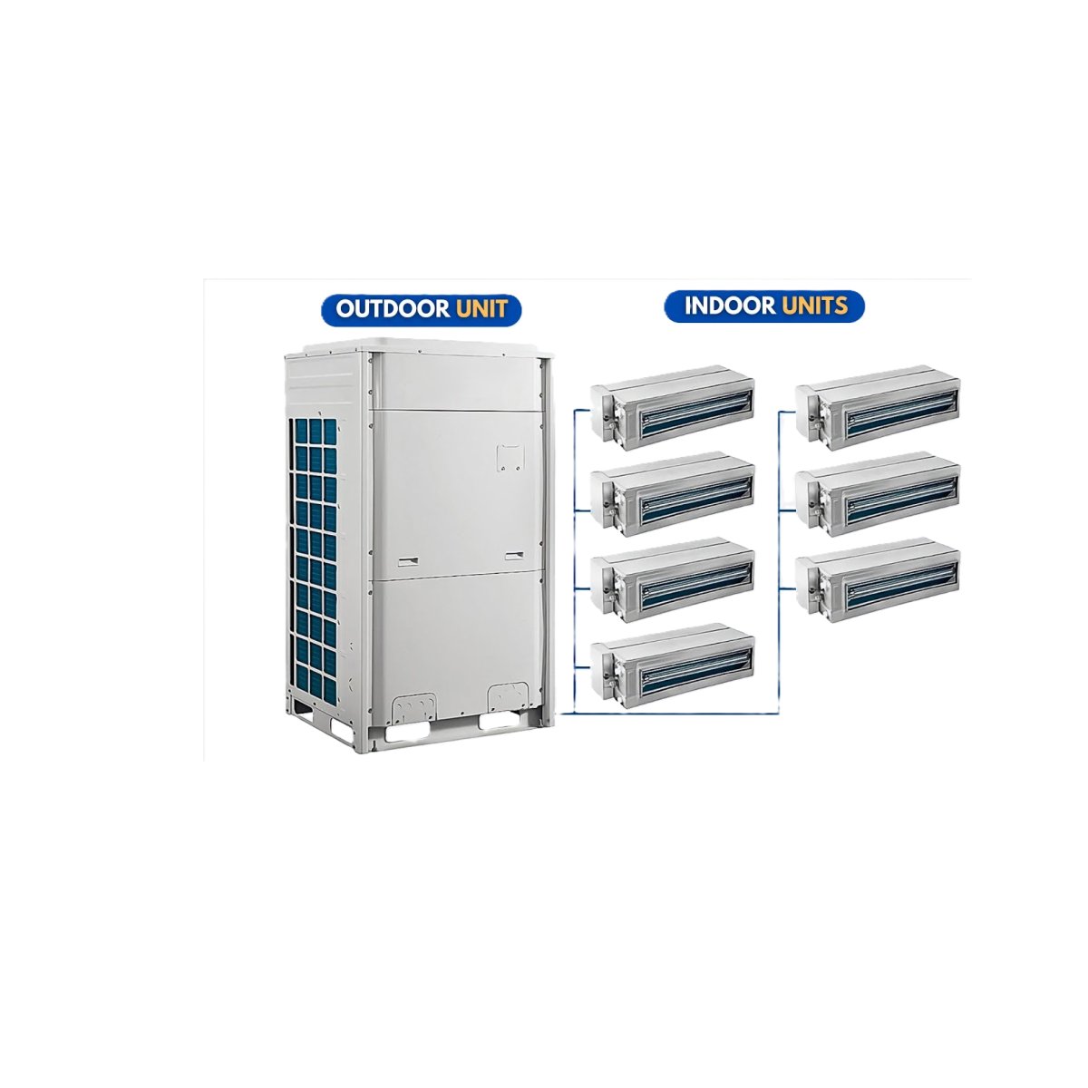
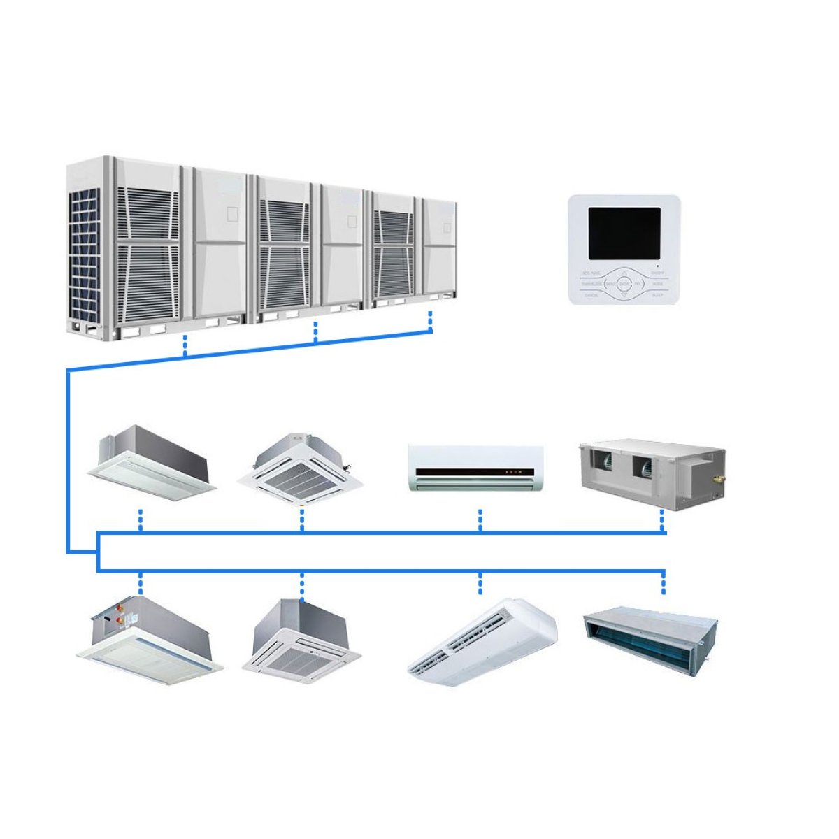
A Variable Refrigerant Flow (VRF)—traditionally trademarked by its inventor Daikin as Variable Refrigerant Volume (VRV)—is an advanced, direct-expansion (DX) commercial climate control system that links multiple independently controlled indoor fan coils to a single external condensing unit. By utilizing inverter-driven variable-speed compressors and electronic expansion valves, a VRF system dynamically scales the volume of circulating refrigerant to match the exact, real-time thermal load of each specific building zone, drastically improving energy efficiency while facilitating simultaneous heating and cooling.
1. Core Architecture & Operating Principle
Unlike traditional central air conditioners that rely on rigid on/off cycles or centralized chilled water networks, VRF systems achieve precision control by circulating variable amounts of refrigerant directly to individual zone evaporators.
Inverter-Driven Compressor: The core engine of the outdoor unit. Instead of shutting down completely when a room reaches its setpoint, the compressor dynamically modulates its motor frequency (and thus its speed) down to as low as $6\%$ to $10\%$ of its maximum output. This eliminates massive electrical inrush currents ($LRA$) and perfectly matches building load fluctuations.
Refnet Joints & Piping Network: The main refrigerant loop branches out into individual rooms using specialized, engineered Y-shaped copper fittings called Refnet joints. These ensure smooth, laminar refrigerant distribution without creating structural pressure drops.
Electronic Expansion Valves (EEVs): Every indoor fan coil unit is equipped with its own microprocessor-controlled EEV. Based on localized temperature sensor data, the EEV narrows or widens its internal valve opening down to precise micro-steps, letting in the exact volume of liquid refrigerant required to meet that room's specific thermostat setting.
2. Technical System Configurations
VRF systems are engineered around specific thermal profiles and fall into three distinct plumbing configurations:
Configuration TypePipe LayoutOperational CapabilityIdeal ApplicationCooling-Only2-Pipe SystemProvides dedicated cooling across all connected indoor heads.Server rooms, tropical climates, or facilities with constant internal heat gains.Heat Pump2-Pipe SystemCan provide either full heating or full cooling across the building, but cannot perform both simultaneously. All zones must share the same seasonal mode.Open-plan offices or residential complexes with uniform, synchronized heating and cooling requirements.Heat Recovery (VRF-HR)3-Pipe System (or 2-pipe with proprietary selection boxes)Provides simultaneous heating and cooling across different rooms on the exact same loop by actively repurposing rejected thermal energy.Hotels, hospitals, and glass-facade offices where south-facing rooms require cooling while north-facing rooms require heating.The Heat Recovery Mechanism
In a 3-pipe Heat Recovery framework (consisting of a high-pressure liquid line, low-pressure gas suction line, and high-pressure hot gas discharge line), the system acts as an energy exchanger. If Room $A$ is too hot, its indoor coil absorbs heat, turning liquid refrigerant into hot gas.
Instead of dumping this hot gas outdoors via the condenser fan, a specialized Branch Selector Box diverts that hot gas directly to Room $B$, which is calling for heat. The hot gas condenses in Room $B$'s coil, heating the room while turning back into liquid to feed Room $A$'s cooling cycle, resulting in an exceptionally high system Coefficient of Performance (COP).
3. Engineering Advantages over Chilled Water System
Large commercial structures traditionally choose between a hydronic Chilled Water System (Chillers, Boilers, Pumps) or a VRF architecture:
Elimination of Distribution Losses: Chillers must cool down a secondary medium (water) and pump it through massive insulated pipes, losing thermal energy along the way. VRF utilizes direct expansion ($DX$), flashing the primary refrigerant inside the room's localized atmosphere for superior thermodynamic heat transfer.
Space Optimization: Heavy, large-diameter hydronic lines and bulky sheet metal air ducts require immense ceiling plenum clearance. Small-bore insulated copper refrigerant lines require a fraction of the structural space, freeing up valuable vertical clearance in high-rise constructions.
True Decentralization & Redundancy: Larger VRF systems often couple multiple modular compressors together. If one outdoor compressor undergoes mechanical failure, the system automatically rotates the load to the remaining operational compressors, maintaining building climate control until repairs are scheduled.