
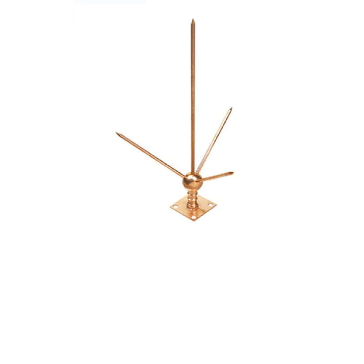
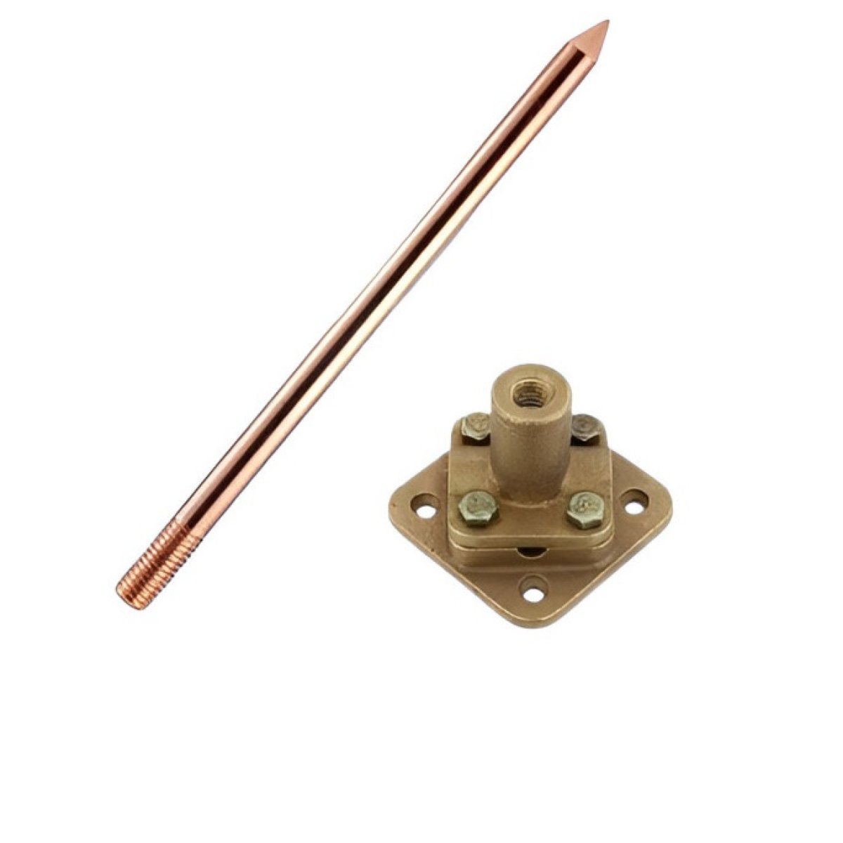
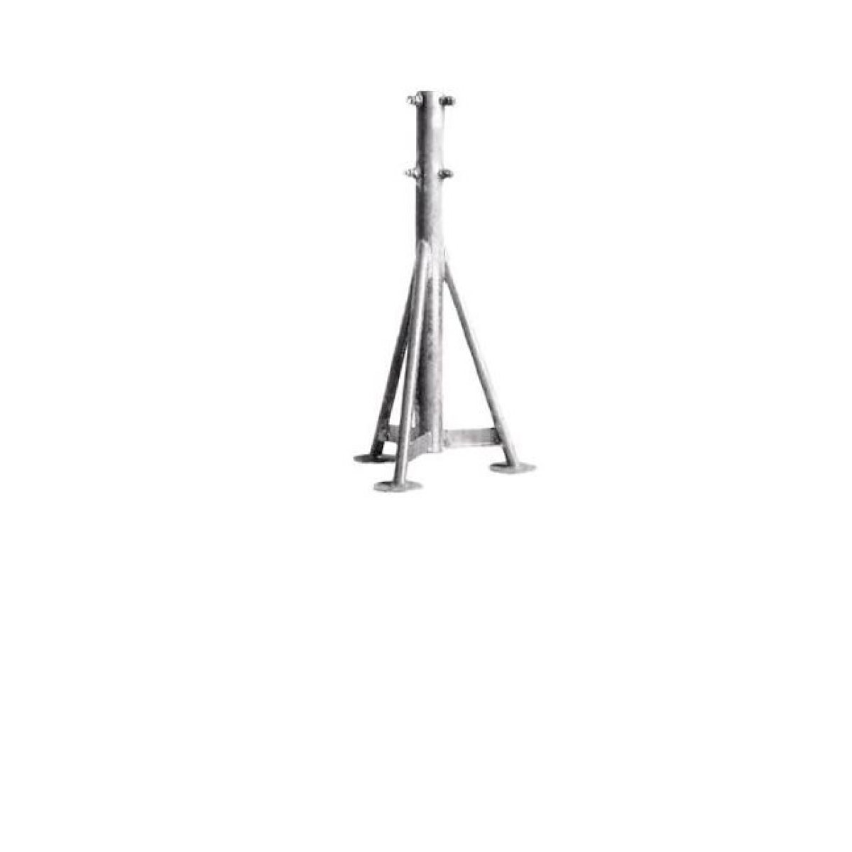
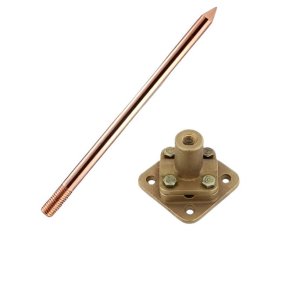
A Down Conductor is the intermediate, high-capacity pathway within an Earthing Protection System (EPS) that links overhead air terminals (lightning rods) directly to the subterranean grounding grid. Its primary engineering function is to safely route the massive electrical current and intense high-frequency electromagnetic energy of a lightning strike down the exterior of a building, preventing the energy from jumping inward (side-flashing) into the structure's internal electrical wiring, structural steel, or personnel.
1. Material Mechanics & System Sizing
Because down conductors must handle massive instantaneous currents—frequently exceeding 100,000 Amperes—within microseconds, they are heavily regulated by international standards (such as NFPA 780 and IEC 62305).
Physical Profiles: Down conductors are typically manufactured as thick, heavy-duty flat metal tapes or multi-strand braided cables. They are primarily constructed from high-conductivity Electrical-Grade Copper or Structural Aluminum, selected carefully to match the building's facade materials and prevent galvanic corrosion.
Cross-Sectional Mass: To survive the extreme thermal dissipation generated by a lightning strike without melting, a copper down conductor must maintain a strict minimum cross-sectional area (typically 50 mm² under IEC codes or a minimum weight of 278 g/m under NFPA Class I rules).
2. Structural Routing & Inductive Impedance Rules
Lightning is not standard low-frequency utility power; it is an ultra-fast transient surge with a rise-time measured in nanoseconds, meaning it behaves like a high-frequency radio frequency (RF) signal. Consequently, physical routing geometry is critical:
The Rule of Sweeping Bends: Down conductors must follow straight, vertical paths down to the earth wherever possible. If they must navigate around architectural ledges, parapets, or roof overhangs, all bends must be broad and sweeping, maintaining a minimum bend radius of 20 centimeters (8 inches) and a maximum interior turn angle of 90 degrees.
The Physics of Side-Flashing: If a down conductor features a sharp, jagged bend, the high-frequency current sees that bend as a massive inductive bottleneck (high impedance $Z$). Instead of following the wire around the sharp corner, the millions of volts of electrical potential will violently punch through air, concrete, or brick walls to jump onto internal metal pipes, structural rebar, or electrical lines. This destructive phenomenon is known as Side-Flashing.
3. Installation Architecture & Testing
To ensure the integrity of the lightning pathway over decades of weathering, down conductors incorporate specific hardware components:Component TypeMechanical FunctionRegulatory Compliance RequirementEquidistant SpacingMultiple down conductors must be installed around the perimeter of the structure to split the lightning current evenly.Spaced every 20 meters (65 feet) for IEC Class I structures; every 30 meters (100 feet) for standard buildings.Bonding ClampsHeavy-duty mechanical fasteners used to tightly clamp the conductor tape to the building envelope.Must be anchored securely at vertical intervals of no more than 1 to 1.5 meters to prevent the wire from violently whipping during a strike due to intense magnetic forces.Test Couplings (Disconnects)A specialized, removable mechanical junction splice positioned roughly 1.8 meters above ground level on each down line.Allows technicians to physically unbolt the down conductor from the earth grid to perform annual low-resistance earth testing without interference from the upper roof network.Structural Rebar IntegrationUtilizing the internal structural steel reinforcement bars (rebar) of a poured concrete high-rise as natural down conductors.The rebar matrix must be continuously welded or structurally tied together to ensure flawless electrical continuity from roof to foundation.