
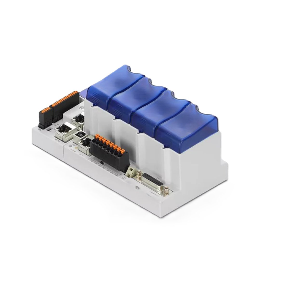
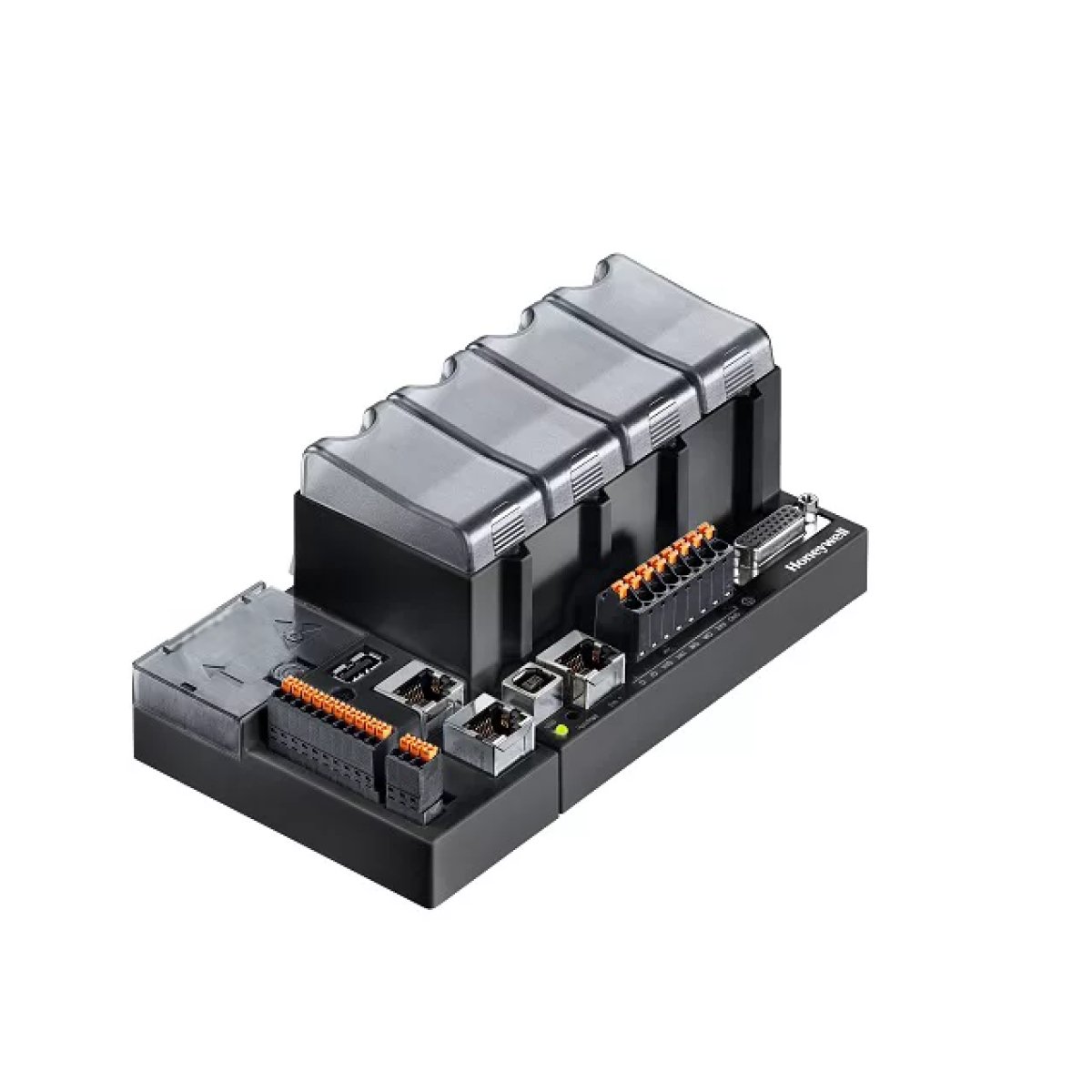
The industrial workhorse of automation and machinery control.
Programmable Logic Controllers (PLCs) are industrial-grade microprocessors engineered to monitor inputs from machinery, execute custom control logic, and drive outputs to precisely automate manufacturing processes, assembly lines, and heavy equipment with extreme reliability.
A PLC acts as the command center for industrial machinery. It operates on a continuous, ultra-fast loop called a scan cycle: it reads the status of connected inputs (like proximity sensors or limit switches), executes a user-programmed logic routine, and immediately updates connected outputs (like starting a motor or opening a hydraulic valve).
PLCs are designed for real-time applications where a delay of even a few milliseconds could disrupt a high-speed production line or cause a safety hazard.
How a PLC Operates: The Scan Cycle
A PLC executes its program in a continuous three-step cycle, typically repeating hundreds of times per second:
Input Scan: The PLC checks the status of all connected input devices and stores this data in its memory.
Program Execution: The microprocessor runs the user-defined control logic (most commonly written in Ladder Logic).
Output Scan: The PLC updates the physical output devices based on the results of the program logic.
System Architecture
A standard PLC system consists of five core components:
The Processor (CPU): The brain that stores the program and executes the math and logic operations.
Input Modules: Interfaces that receive signals from field devices like push-buttons, temperature sensors, photo-eyes, and encoders.
Output Modules: Interfaces that send commands to field devices like relays, motor starters, solenoid valves, and indicator lights.
Power Supply: Converts incoming AC voltage to the low-voltage DC power required by the PLC’s internal circuitry.
Programming Device: A computer running specialized software (e.g., Rockwell Studio 5000 or Siemens TIA Portal) used to write, debug, and download the automation code to the CPU.