
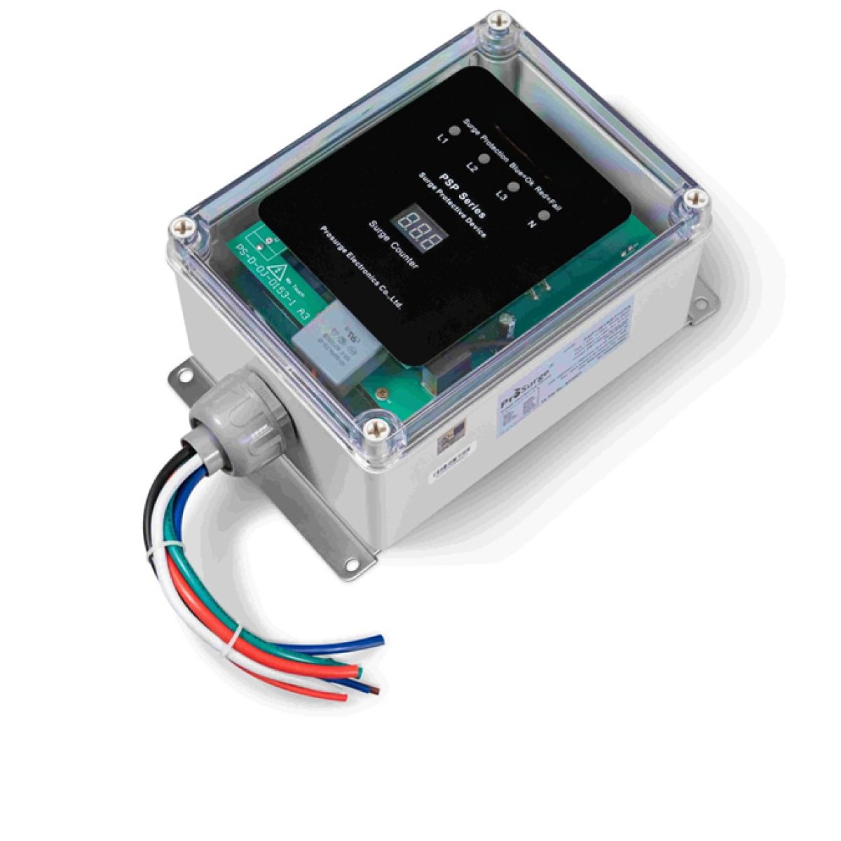
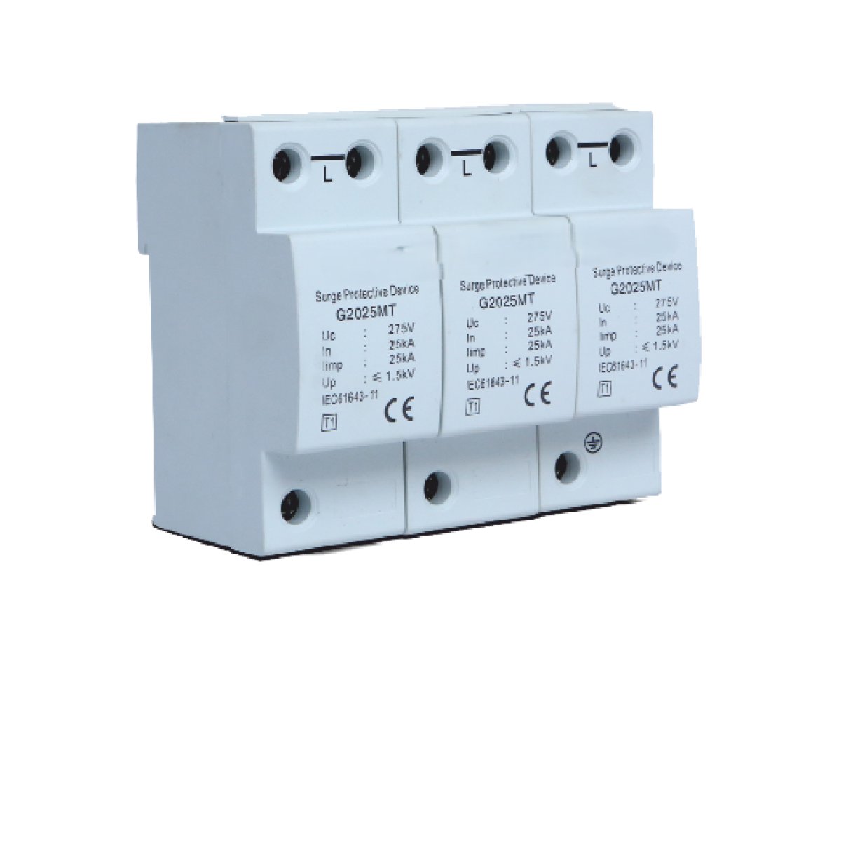
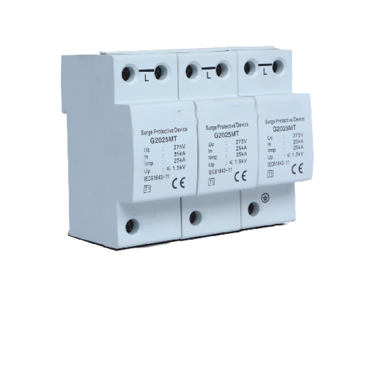
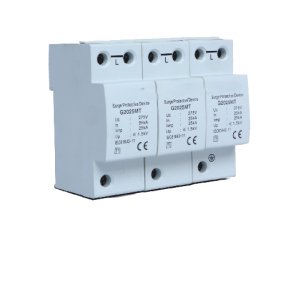
A Surge Protection Device (SPD) is a specialized electrical safety component engineered to protect sensitive electronic equipment, appliances, and industrial controls from transient voltage surges. Operating as a high-speed, voltage-sensitive switch, an SPD continuously monitors the electrical line; the instant it detects a dangerous, microsecond-duration voltage spike (caused by lightning strikes, utility grid switching, or heavy motor cycling), it drops its internal resistance to divert the destructive excess energy safely to the grounding grid before it can reach and destroy downstream loads.
1. Internal Component Technologies
To respond to voltage spikes that materialize and peak within nanoseconds, SPDs rely on solid-state materials that exhibit highly non-linear electrical resistance properties.
Metal Oxide Varistors (MOVs): The most prevalent technology used in power lines. An MOV consists of a matrix of zinc oxide grains compressed between two conductive plates.
Normal Operation: At standard line voltages (e.g., $120\text{V}$), the MOV exhibits exceptionally high electrical resistance, acting as an open circuit that blocks current.
Surge Condition: When the voltage cross-section spikes above a critical threshold (the Clamping Voltage), the zinc oxide grains instantly transition into a highly conductive state. Its resistance drops to near zero, shunting the surge current safely to the ground.
Gas Discharge Tubes (GDTs): These feature two electrodes enclosed inside a sealed ceramic chamber filled with an inert gas. When a high-voltage transient hits, the gas ionizes, transforming into a highly conductive plasma arc that bleeds off massive current loads. GDTs can handle significantly higher surge currents than MOVs, but they take slightly longer to trigger, making them ideal for incoming telecom and main utility lines.
Transient Voltage Suppression (TVS) Diodes: A precision semiconductor silicon diode. TVS diodes respond with hyper-speed (in the picosecond range) and offer highly precise voltage clamping, but they possess limited current-handling mass, making them perfect for protecting delicate microprocessors on internal circuit boards.
2. The Cascaded Protection Topology (Class I, II, III)
A single surge protector at an outlet cannot insulate a facility from a major electrical event. Comprehensive engineering requires a multi-tiered, cascaded deployment strategy defined by standards like IEC 61643 and UL 1449.Type 1 / Class I (Main Service Entrance Protection)
Installed directly at the primary electrical service utility entrance or the main distribution transformer hub.
Objective: Designed to handle severe, high-energy external transients, specifically raw, direct, or nearby lightning strikes. They are rated to withstand heavy $10/350\,\mu\text{s}$ current waveforms.
Type 2 / Class II (Sub-Panel Distribution Protection)
Installed at downstream sub-panels throughout a facility.
Objective: Protects localized branch circuits from remnant energy passed by the Type 1 device, as well as absorbing the frequent internal surges generated within the building by large inductive loads (like central AC compressors, elevator motors, or industrial pumps cycling on and off). They utilize an $8/20\,\mu\text{s}$ impulse rating.
Type 3 / Class III (Point-of-Use Protection)
The final line of defense, situated directly at the equipment plug interface (e.g., surge strips, specialized receptacles).
Objective: Provides ultra-fine, low-voltage clamping protection tailored for hyper-sensitive local electronics like servers, medical imaging devices, and programmable logic controllers (PLCs).
3. Key Technical Specification Metrics
When specifying an SPD for an infrastructure network, engineers evaluate four critical electrical thresholds:Specification MetricEngineering DefinitionOperational Significance$MCOV$ (Maximum Continuous Operating Voltage)The absolute maximum root-mean-square ($RMS$) voltage that the SPD can handle continuously without triggering or degrading.Must be sized at least 15% to 25% higher than the nominal utility voltage to prevent the device from burning out during minor, non-hazardous grid fluctuations.$I_n$ (Nominal Discharge Current)The peak surge current ($8/20\,\mu\text{s}$ wave) that the SPD can successfully endure for $15$ consecutive strikes without failing.A primary metric determining the overall robust lifespan and reliability classification of the device under heavy-use conditions.$V_p$ / $V_PR$ (Voltage Protection Rating / Clamping Voltage)The maximum voltage level that the SPD will allow to pass downstream through to the protected equipment during a surge event.The lower this number is, the better the protection. The rating must always fall well below the maximum insulation breakdown voltage of the connected load.Thermal Disconnection NetworkAn internal safety mechanical spring mechanism paired with a low-temperature solder link.MOVs naturally degrade with every surge they absorb. When an MOV reaches its end-of-life, it begins to leak current and overheat. The thermal link melts, physically snapping the degraded MOV out of the circuit to prevent the device from catching fire.